Electrical System |
|
|||
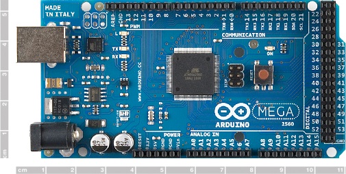
The autonomy of the kayak is controlled with an ATmega2560 Microcontroller Board, the Arduino Mega 2560. It performs the following tasks:
Sensors: GPS, tilt-compensated compass, yaw-rate gyro, temperature and humidity of electrical enclosure Communication: Digi Xbee RF wireless mesh network and point-to-point capabilities Thruster control: Thruster PWM signal sent to 28-amp motor driver, servo control sequence sent directly to servo Power system: Lithium-polymer battery pack, switched-mode power supplies at 5 and 12 volts, low-voltage automatic shutdown to prevent battery over-discharge |
 |
 |
||
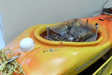
GPS (white device) and Electrical Enclosure |
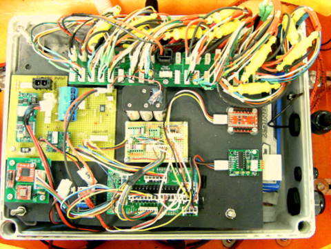
Interior of Elec. Enclosure |
|||
 |
 |
 |
||
Arduino Microcontroller |
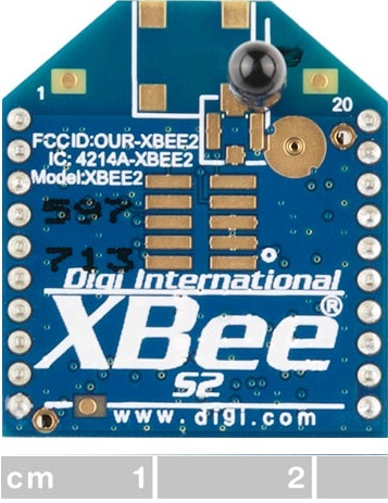
Xbee RF Modem |
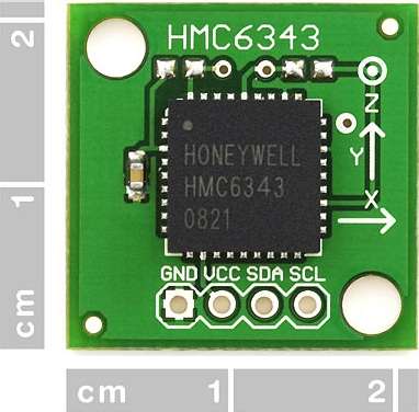
MEMS Compass |
||
Position Control System |
 |
|||
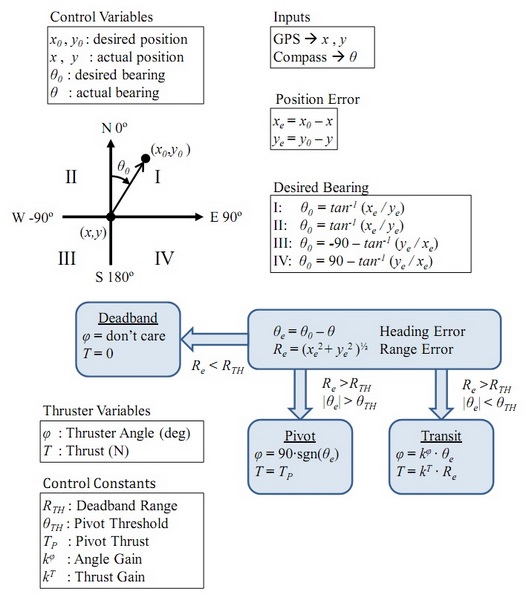
Kayak position is controlled by setting the thrust, T, and thrust angle, φ, using GPS and compass measurements. Depending on the range and heading error, the control system enters one of three modes. Mode 1 - Deadband: If range error is small, the vehicle enters deadband mode and no control actions are performed. If range error is not small, Modes 2 or 3 are used. Mode 2 - Pivot: If heading error is large, pivot mode is used to rotate the vehicle in place until it is aimed towards the target. The thrust angle is set at ninety degrees, and a constant thrust is used until the heading error is adequately reduced. Mode 3 - Transit: If heading error is small, the vehicle uses transit mode with proportional control of heading and thrust. At large range errors, thrust saturates at full output. This is the mode most often in use. |
||||
Description of kayak control system |
||||